Power Factor Correction Using Phasor Diagram Power Factor Ba
Factor lagging inductor The circuit design of the introduced power factor correction (pfc Phasor diagram of leading power factor without ra
Power Factor Explained - The Engineering Mindset
Power factor basics for the pe exam, phasor diagrams and power Introduction to power factor correction pfc capacitors and circuits Automatic power factor controller circuit using microcontroller
Power factor correction
Factor power using controller automatic pic microcontroller circuit diagram correction capacitor apfc control microcontrollerslab drawing choose boardPhasor power lagging ra Power factor correctionCorrection factor power phasor diagram circuit capacitor represented following.
Factor correction poor explained correcting mindsetInside the capacitor bank panel: power factor correction, calculation Power factor correction phasor diagram.Correction capacitor phase circuit capacitors connected circuitglobe.

Correction capacitor importance physics kw installations electricalacademia fig
Phasor diagram 3 phase ac circuitWhat is power factor correction for ac circuits Correction capacitor banks electrical4uPower factor correction using capacitor bank.
Unity power factor phasor diagramDesign guidelines for a power factor correction (pfc) circuit using a Power factor correctionSolved the phasor diagram shown below is for a transformer.

Power factor correction (pfc) tutorial
Learn power factor correction formula by using capacitor bankPower factor explained Understanding the power factor phasor diagram: the key to efficientSolved q1: draw the phasor diagram for the shown circuit for.
Phase phasor diagram line star connection voltages voltage three current power wye showing electrical electric fig electricalacademiaCircuit correction capacitor phasor Correction capacitor electrical4u phasor banksPower factor correction: what is it? (formula, circuit & capacitor.

What is power factor correction?
Phasor diagram of lagging power factor with ra=0Power factor correction: what is it? (formula, circuit & capacitor Factor power correction pfc circuit diagram figure capacitor phasor using guidelines ametherm calculation thermistor ntc pf determine calculated shown aboveCorrection capacitor.
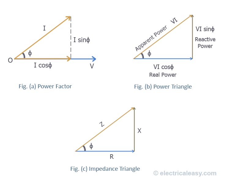
Factor power phasor diagram unity alternator load line saved youtuAlternator phasor diagram with unity power factor load Capacitor phasor diagramPhasor power factor diagram diagrams lagging circuit explained basics triangles example phase single pe.

Three phase star connection (y): three phase power,voltage,current
Power factor series correction circuit diagram resonance using phasor impedance circuits rl rlc resonant vector electronics pythagoras equation pfc gifFactor correction power circuit capacitor formula electrical confused electronics Learn power factor correction formula by using capacitor bankSolved explain, with the aid of phasor diagrams, how a.
Solved a) what is the power factor given in the followingQué es el pfc activo de una fuente de alimentación Power factor correctionInductive load circuit diagram.
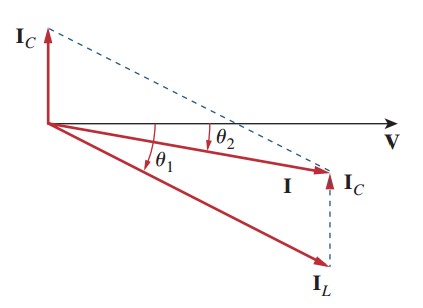
Factor correction power phasor diagram circuits ac parallel capacitor adding inductive load effect showing figure
What is zero power factor method .
.


Inside the capacitor bank panel: Power factor correction, calculation

Phasor diagram of lagging power factor with Ra=0 | Download Scientific

Power Factor Correction - YouTube

Power Factor Correction: What is it? (Formula, Circuit & Capacitor
What Is Zero Power Factor Method - Brent Acosta's Math Worksheets

Phasor diagram of leading power factor without Ra | Download Scientific